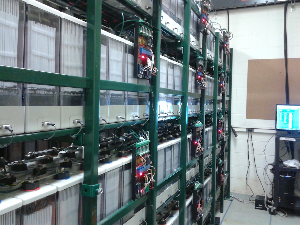
We have a new paper using operando methods to track spinel formation inside batteries while they are discharging. Our work gives important and striking new insight into the MnO2 discharge reaction, by revealing the phase transformations normally hidden within the sealed battery and also pinpointing intermediate phases. We did this using a highly penetrating operando technique, which operates in real time at high battery discharge rate.
The spinels ZnMn2O4 (hetaerolite) and Mn3O4 (hausmannite) are the reason MnO2 cathodes cannot be recharged, and the mechanism by which they form is not agreed upon. One would like to avoid these spinels, and thus it would be great to know how they form. The MnO2 discharge begins as a single-phase proton insertion, written
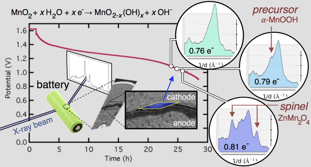
MnO2 + xH2O + xe– → MnO2-x(OH)x + xOH–
The end of the reaction is less easy to write. The MnO2 expands as the tunnels in its crystal structure fill up with protons, and at some point phase transformations are triggered, with MnOOH being the first. After that, the results are highly dependent on the work being reported. Some of the most cited results are given below (discharge products listed on the right in bold).
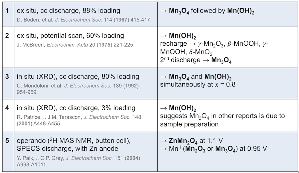
1, 2, and 3 disagree on when Mn3O4 forms, and 4 asserts that it doesn’t form at all and is rather a consequence of taking apart the electrode for analysis. This is important, because Mn(OH)2 can be recharged and is not a problem. 5 includes zinc in the battery, and finds that the zinc and manganese spinels form at different potentials. Clearly the reaction is complicated. (Note that these experiments also differ in electrode construction, type of discharge, and method of observation.)
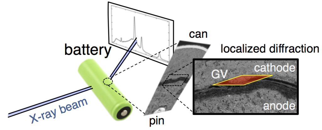
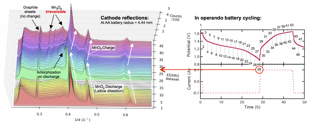
This confusion is why we decided to follow this reaction using high-energy, high-flux X-rays, which can penetrate even large batteries and can also be precisely focused on a specific location. The figure above shows X-ray diffraction data collected in the battery cathode, in a slim region directly next to the separator. From porous electrode theory you expect this to be the most active part of the cathode, and thus the fastest to discharge.
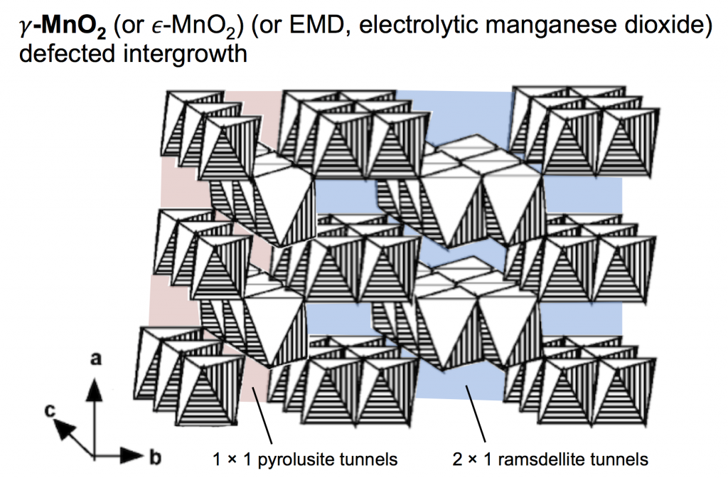
The type of MnO2 used for the proton-insertion written above can be called several different names: electrolytic manganese dioxide (EMD) which is a classification based on how it is produced; γ-MnO2 which is based on the crystal structure; and ε-MnO2 which is similar to γ-MnO2 but with a subtle difference (that we won’t worry about). For this discussion we’ll use the name γ-MnO2, which is a defected intergrowth of pyrolusite (β-MnO2, which has 1 × 1 tunnels in its crystal lattice) and ramsdellite (R-MnO2, which has 2 × 1 tunnels in its crystal lattice). The picture above shows a simple depiction of γ-MnO2, built of MnO6 octahedra that both corner- and edge-share, making a pattern of tunnels. The 2 × 1 ramsdellite tunnels are colored blue, and the pyrolusite tunnels are colored red.
The long and short of it is this: you would like to maintain this structure while cycling the battery. Protons are inserted into the tunnels during discharge, and on battery charge they are removed. Once this structure starts breaking down, the battery no longer performs in the same way, and won’t recharge.

Ramsdellite and pyrolusite lead to different materials when they are fully proton inserted, shown by the following two equations. (α-MnOOH is called groutite, and γ-MnOOH is called manganite. There are quite a few names to remember when dealing with these materials, it is true.)
R-MnO2 + H2O + e– = α-MnOOH + OH–
β-MnO2 + H2O + e– = γ-MnOOH + OH–
Both of these are written with the full extent of reaction, or x = 1 in the equation from before. Each formula unit has gained one electron (MnIV became MnIII) and one proton was inserted (O2 became OOH). The protons reside in the tunnels and hydrogen bond to oxygens across the tunnels, and this shears the crystal structure slightly. If the tunnel projection along the c-direction (shown above for both empty and proton-filled structures) is approximated as a parallelogram, the protons make the acute angles slightly smaller. The dotted lines above illustrate that inserted and non-inserted structures do not match up. For example, groutite and pyrolusite cannot fit together in the same phase.
Now we have arrived at the issue: the ramsdellite and pyrolusite tunnels do not fill with protons at the same rate. One fills faster. This means one of the tunnel domains shears before the other. Since they can’t fit together after that, this also shears the crystal apart, which obviously kills any plan to maintain the structure.
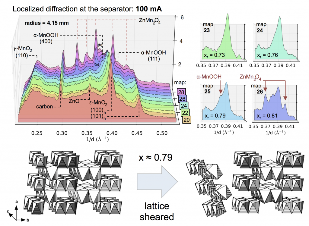
Evolution of the X-ray diffraction pattern inside a discharging battery is shown above in the colorful waterfall plot. The data is collected in a 100 micron wide section directly by the battery separator during galvanostatic discharge at 100 mA. The first appearance of a new crystalline phase is α-MnOOH during the 25th XRD “map” of the cell. This is broken out in the light blue plot on the right, showing the α-MnOOH (400) reflection (with a d-spacing of about 2.66 Å, 1/d = 0.376). The ZnMn2O4 spinel forms directly afterward, and to a great extent. This result was true for every battery discharge rate tested, at every location: the spinel (sometimes ZnMn2O4, sometimes Mn3O4) always immediately followed the the α-MnOOH (400) reflection.
We took this “operando” X-ray diffraction data and combined it with a proven mathematical model for cylindrical Zn-MnO2 batteries. The model allowed us to calculate the local reaction extent at every point, a radius-dependent value of x, written xr. The phase transformation to α-MnOOH alway occurred at xr = 0.79, regardless of the discharge current or location in the battery. (It was actually a range that spanned xr = 0.78-0.81, but 0.79 was by far the most common value.) It was reliable that at xr = 0.79, α-MnOOH formed and then spinel soon followed. This implies that α-MnOOH, which has sheared apart from the rest of the crystal structure, is the precursor to spinel, and that spinel formation is not potential-dependent, contradicting the conclusions of refs. 4 and 5 above. Mn(OH)2 never formed, showing that in this situation Mn3O4 was clearly preferred, contradicting refs. 1-3.
After the full analysis the new insights into γ-MnO2 proton insertion were:
- At all locations in the cathode, well-formed α-MnOOH occurred after insertion of 0.79 H+ per Mn atom (xr = 0.79).
- Well-formed γ-MnOOH was never observed, despite a substantial fraction of pyrolusite in the starting material.
- Mn(OH)2 did not form, due to the high mass loading of γ-MnO2 used. The Mn(OH)2 formation mechanism requires a higher amount of conductive surface.
- Insertion of 0.79 H+ correlated to 104% of the ramsdellite tunnel capacity (0.76), although the ramsdellite was not fully-filled when the α-MnOOH phase was detected (i.e. the α-MnOOH was non-stoichiometric). The formula of the newly-formed α-MnOOH could not be precisely calculated, but was estimated to be greater than α-MnOOH0.88.
- Spinel, either ZnMn2O4 (near separator) or Mn3O4 (cathode interior), formed immediately following α-MnOOH in all cases.
- Spinel formed at the expense of α-MnOOH, confirming α-MnOOH is the reactant.
- The bottom line, informing battery engineering with MnO2 materials chemistry: avoid the α-MnOOH phase transition, and the battery will remain rechargeable.
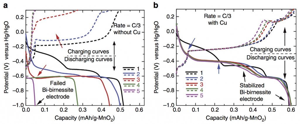
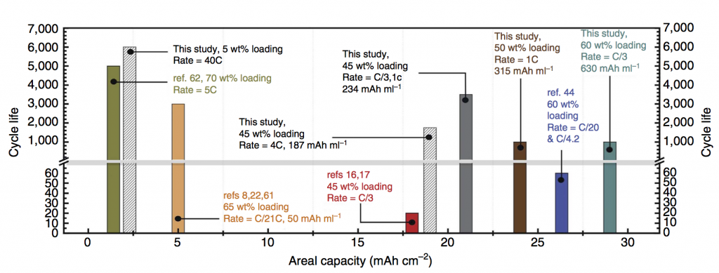
 Some exciting news: we have a new paper out in Nature Communications featuring a deep cycling manganese dioxide (MnO2) cathode. This cathode is aqueous, operating for thousands of cycles in KOH electrolyte, at essentially the full 2-electron capacity of MnO2, which is 617 mAh/g-MnO2. MnO2 is abundant, inexpensive, and non-toxic, making it an ideal basis material for large-scale batteries at the scale of the power grid. Batteries on this scale will make widespread use of solar and wind power possible in the future. Because the electrolyte is water-based, the resulting battery is inherently safer than Li-ion, which relies on a highly flammable electrolyte. Fires caused by Li-ion batteries in small devices like cell phones are a generally accepted risk, but for massive stationary batteries located in power grid infrastructure the risk assessment recommends using a safer, water-based battery chemistry.
